1. Background
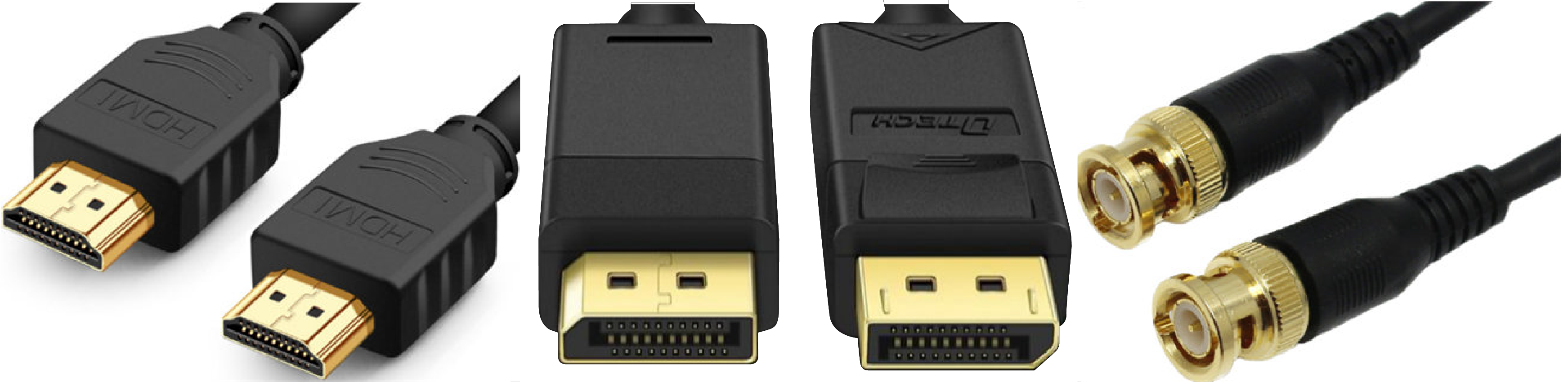
1.1. Shortage of traditional video signal transmission solution
1. They can't transmit signals over long distances without quality loss.
2. Different connectors provide different bandwidths.
3. 4K and 8K cables are costly, thick, and hard to handle.
4. Cable connectors are easily damaged and hard to fix.
1.1. Shortage of traditional video signal transmission solution
Optical fiber transmission is ideal for long distances and offers several advantages over traditional cables:
1. Longer Transmission Distance: Fiber optics offer longer, more stable transmission with less loss and stronger resistance to electromagnetic interference.
2. Lower Cost: Fiber optics and optical modules are more affordable and user-friendly.
3. Easier Maintenance: In a setup of two optical modules and one optical fiber, issues can be easily fixed by replacing the damaged component.
The PIXELHUE & NovaStar transmission solution utilizes standard SFP+ connectors, offering a mature, stable, and efficient method for long-distance video transmission. It outperforms traditional cable transmission in terms of distance, portability, cost, and maintenance.
Features | Traditional Cables | Optical Fiber Cables with Built-in Video Interfaces | Nova's Video Signal Optical Fiber Transmission Solution |
|---|
Transmission Distance | Short (around 1-30m, SDI can reach 200m) | Modermiate (around 100m-150m) | Long (single-mode optical modules together with fibers: 10km) |
Cost | Low, proportional to distance | High | Moderate |
Maintenance | Replace the entire unit if damaged | Replace the entire unit if damaged | Replace the damaged component only |
2. Optical Transmission Knowledge Highlights
2.1 Characteristics and differentiation methods of single-mode and multi-mode optical modules
2.1.1 Differences between single-mode and multi-mode optical modules
Differences | Single-mode Optical Modules (recommended) | Multi-mode Optical Modules |
|---|
Wavelength | 1310nm & 1550nm | 850nm (around 100m-150m) |
Transmission Distance | (1) 1310nm single-mode optical modules: within 40km, usually 10km;
(2) 1550nm single-mode optical modules: over 40km. | 300m |
2.1.2 Optical module parameter interpretation and differentiation methods
Parameter interpretation:
As shown in Figure 2.1 and Figure 2.2, optical modules are labeled with tags that indicate their parameters.
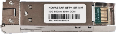
Figure 2.1
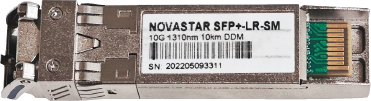
Figure 2.2
Figure 2.1 shows a multi-mode optical module. Figure 2.2 shows a single-mode optical module. The label on an optical module typically includes following parameters that indicate its specifications.
Parameters | Explanation |
|---|
SFP+ | The package type of the optical module |
10G | The data rate transmitted by the optical module |
1310nm/850nm | The wavelength of the optical module. Generally, 1310nm is used for single-mode optical modules and 850nm for multi-mode optical modules. |
LR/SR | LR stands for Long Range;
SR stands for Short Range. |
MM/SM | MM stands for multi-mode;
SM stands for single-mode. |
10km/300m | The transmission distance. Generally, 10km is used for single-mode optical modules and 300m for multi-mode optical modules. |
Differentiation Methods:
Check the lable on the optical module and identify by the wavelength, transmission distance and other parameters;
2.2 Characteristics and differentiation methods of single-mode and multi-mode fibers
2.2.1 Differences between single-mode and multi-mode fibers
Differences | Single-mode Optical Modules (recommended) | Multi-mode Optical Modules |
|---|
Core Diameter/Cladding Diameter | 9um/125um, with a thin fiber core | 50um/125um or 62.5um/ 125um, with a thick fiber core |
Optical Mode | Transmits only one optical mode | Transmits multiple optical modes |
Transmission Distance | Long distance transmission, over 10km | 300m-500m |
2.2.2. Fiber optic line mark parameter interpretation and differentiation methods
Parameter interpretation:
As shown in Figures 2.3 and Figure 2.4, the cladding of the fiber will have a mark after production. This mark differs between armored and unarmored fibers, as demonstrated in the following examples.

Figure 2.3
Figure 2.3 shows an illustration of the mark on an unarmored fiber optic cord.
The general format of the mark on unarmored fiber is "OPTICAL FIBER CABLE MM 50/125um OM3-PVC-02/2018 0135M".
Parameters | Explanation |
|---|
02/2018 | MM stands for multi-mode; SM stands for single-mode. |
PVC | Core diameter/Cladding diameter |
OM3 | OMx stands for 10 Gigabit multi-mode; OSx stands for 10 Gigabit single-mode. |
50/125um | The material of the outer layer |
MM/SM | Date of manufacture |
0135M | Length markings (meter markings) |

Figure 2.4
3. PIXELHUE & NovaStar's Optical Transmission-enabled Devices and Usage Methods
3.1 Introduction to PIXELHUE devices
3.1.1 P20 Seamless Switcher
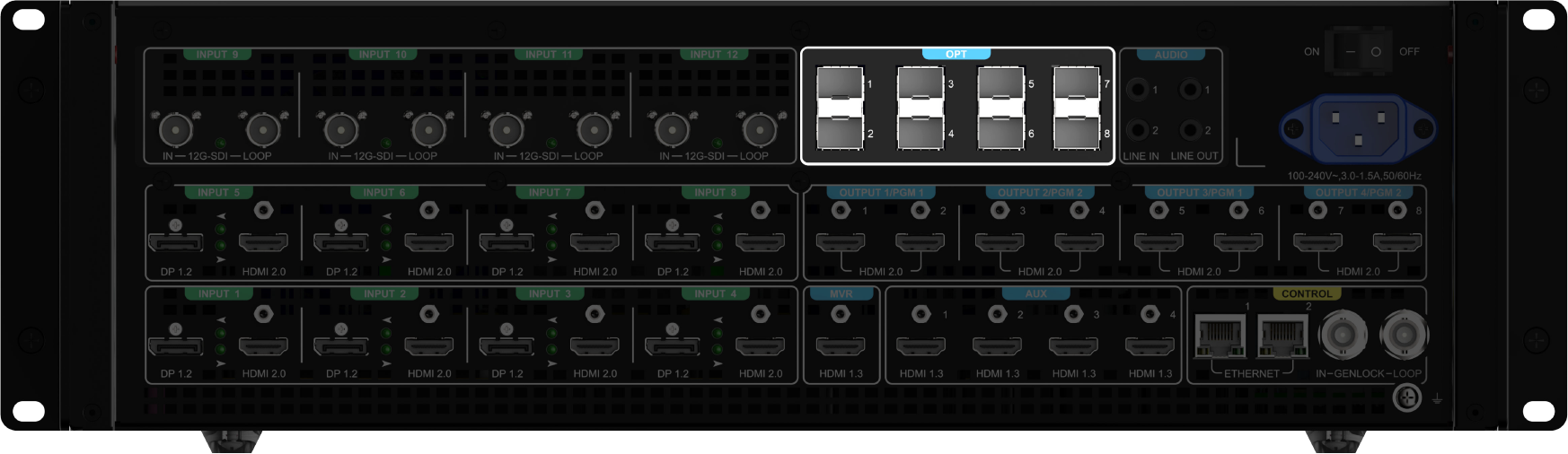
Figure 3.1
Maximum Capacity Supported by a Single Optical Port | Maximum supports for DL output |
Maximum Datas Supported for All Optical Ports | Switcher mode: supports up to 2*4k outputs or 4*DL outputs;
PGM Only mode: supports up to 4*4k outputs or 4*DL outputs;
where 4k is achieved by the upper and lower optical ports spliced left and right. |
The P20 features 8 optical port outputs, with the specifications detailed in the table below.
3.1.2 P10 Seamless Switcher
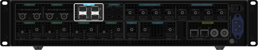
Figure 3.2
The P10 features 4 optical port outputs, with the specifications detailed in the table below.
Maximum Capacity Supported by a Single Optical Port | Maximum supports for DL output |
Maximum Specifications Supported for All Optical Ports | Switcher mode: supports up to 1*4k output or 2*DL outputs;
PGM Only mode: supports up to 2*4k outputs or 4*DL outputs;
where 4k is achieved by the upper and lower optical ports spliced left and right, and the DL by two SL outputs spliced together. |
3.1.3 Q8
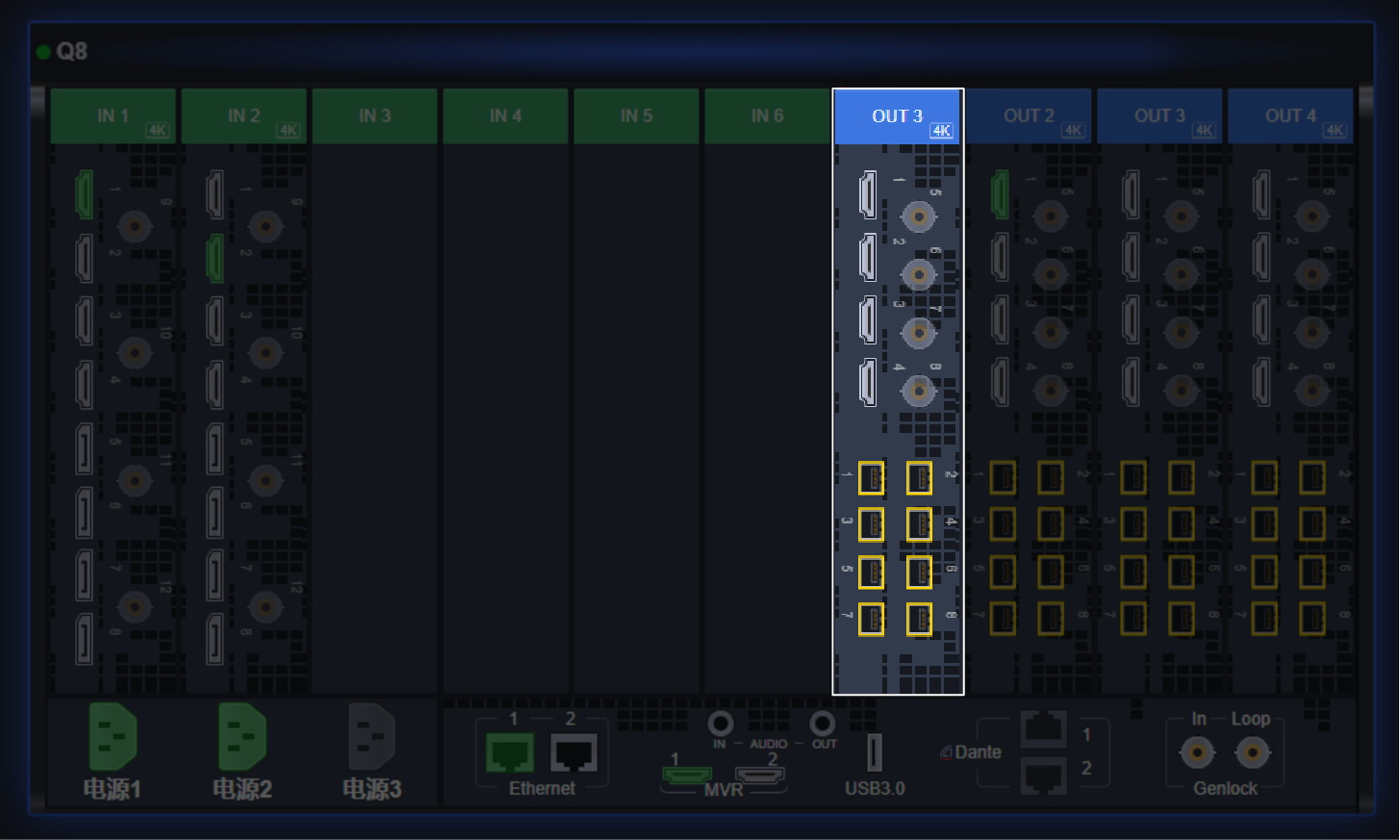
Figure 3.3
Maximum Capacity Supported by a Single Optical Port | Maximum supports for DL output |
Maximum Specifications Supported for All Optical Ports | Supports up to 4*4k outputs,where 4k is achieved by two optical ports in each row spliced left and right. |
3.1.4 F8/F4
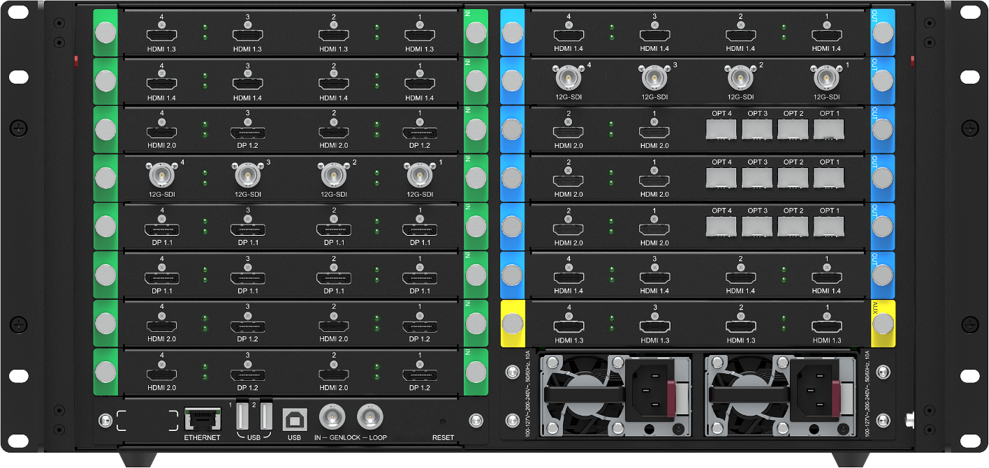
Figure 3.4
Maximum Capacity Supported by a Single Optical Port | Maximum supports for DL output |
|---|
Maximum Specifications Supported for All Optical Ports | Maximum Specifications Supported for All Optical Ports Supports up to 1*4k output, spliced from optical ports 1 and 2, with optical ports 3 and 4 duplicating optical ports 1 and 2;
Supports up to 2*DL outputs, with optical port 3 duplicating optical port 1 and optical port 4 duplicating optical port 2. |
3.2 NovaStar's optical transmission-enabled receiving devices
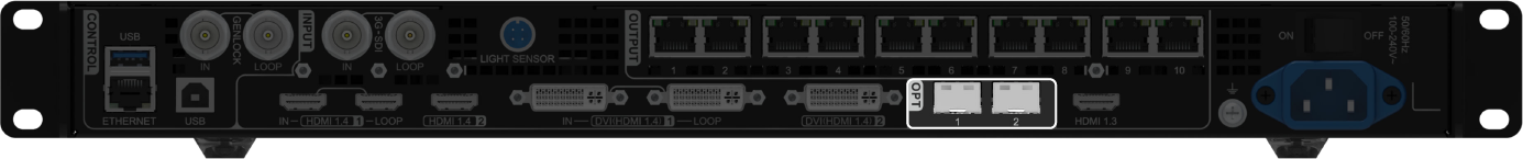
3.2.1 NovaPro UHD Jr
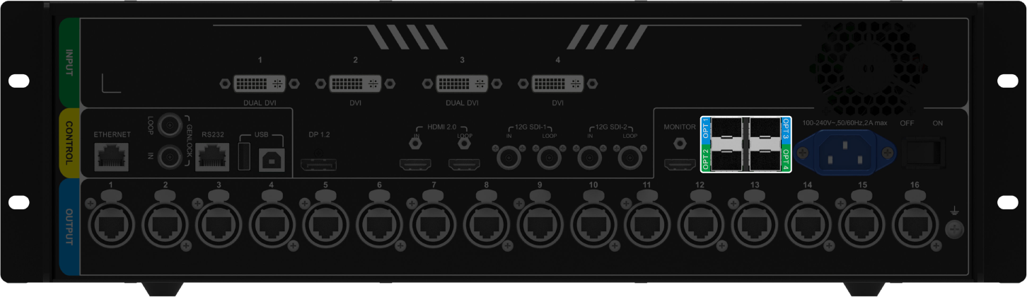
Figure 3.5
The NovaPro UHD Jr features 4 optical port outputs.
Maximum Capacity Supported by a Single Optical Port | Optical port 1 supports maximum DL input;
Optical port 2 supports maximum DL input and output;
Optical port 3&4 lack video source receiving capability. |
|---|
The difference in Loop-out Mode of OPT Port | Non-LOOP mode of video controller mode: optical port 1 and optical port 2 will receive video signals that sent from other transmission devices that also support optical transmission functions, the maximum;
Maximum support DL capacity video sources;
LOOP mode of video controller mode: optical port 2 will output the video source that input by optical port 1. |
3.2.2 VX1000/VX600/VX400
The VX series feature 2 optical ports.
Maximum Capacity Supported by a Single Optical Port | Optical port 1 supports maximum DL input;
Optical port 2 lacks video source receiving capability. |
3.2.3 H-Series Optical Input subcard

Figure 3.6
Maximum Capacity Supported by a Single Optical Port | Supports maximum DL input |
Backup Relationship of Optical Ports Optical port 3 backs up optical port 1, and optical port 4 backs up optical port 2. | Optical port 3 backs up optical port 1, and optical port 4 backs up optical port 2. |
3.3. Typical application scenarios and environment construction of NovaStar's optical transmission program
The P20 works with the NovaPro UHD Jr:
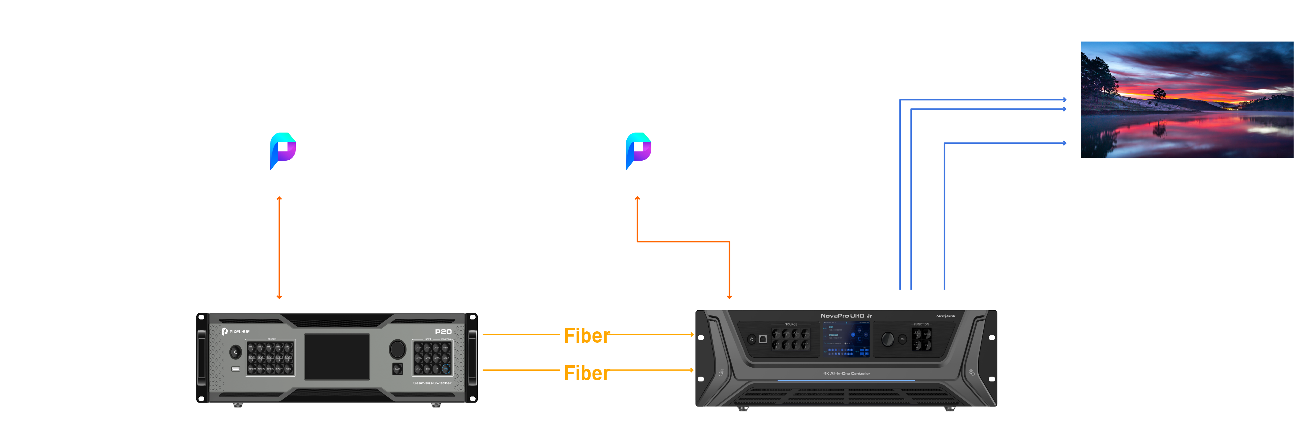
Figure 3.7
As shown in Figure 3.7, the input source is connected to the P20. After professional processing by the P20, the video is transmitted via fiber optic to the JR. The JR receives the video through the optical port, processes it, and displays it on the LED screen. The collaboration between the professional video processor P20 and the NovaPro UHD JR controller ensures the optimal on-screen effect.